Temperature and humidity
Pins, pins, pins
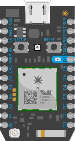
Before we add these sensors, it helps to know a little bit more about the pins on the Particle Photon. This will not be a deep dive but just enough to get your feet wet. If you look at the Photon, you will see the pins at the left and right edges with labels such as 3V3, GND, D0 to D7, A0 to A5 and more:
If you have the Photon with headers or you soldered the headers yourself, you should mount the Photon on a breadboard to be able to carry signals to and from the pins on the device with ease. The picture below shows my Photon on a small breadboard with a wire from 3V3 (power; 3.3 volts) to the + rail on the breadboard, and a wire from GND to the - rail on the breadboard. The Photon is powered with a micro USB cable connected to a wall plug or to a computer. If you are not comfortable with terms such as power and ground, take a look at https://learn.sparkfun.com/tutorials/electric-power.
<PICTURE HERE WITHOUT SENSOR>
The reason you use a breadboard is to easily connect sensors when prototyping. Connecting the Photon's power (3V3) and ground (GND) pins to the power and ground rails on the breadboard, makes it easy to provide power and ground to sensors as well. The picture below has the power and ground wires connected to the appropriate rails on the breadboard.
<PICTURE HERE WITH SENSOR CONNECTED>
Before proceeding, let's examine the difference between a digital pin and an analog pin. Depending on the sensor, you often have to use one or the other. A digital pin can have two states: HIGH (1) or LOW (0). You either read from the pin and obtain the HIGH or LOW value, or you write the HIGH or LOW value to the pin. To write the HIGH value to digital pin D1, you would use the following code snippet:
pinMode(D1, OUTPUT);
digitalWrite(D1, HIGH);
Yes, that's all there is to it. You first use the pinMode function to indicate you want to write to the pin. The default pinMode is INPUT. The second function, digitalWrite is then used to write the HIGH value. At the power level, the call to the above digitalWrite function results in 3.3V being sent from the pin to whatever is connected to it. If you write the low value, 0V is sent. A digitalWrite can be used for example to turn a connected LED on or off.
To read from a digital pin, just use:
value = digitalRead(D1)
A digitalRead can be used for example to detect if a button was pressed as in the following example which turns on a LED when a button connected to D1 is pressed:
pinMode(D1, INPUT);
pinMode(D2,OUTOUT);

 if ( digitalRead(D1) == HIGH  ) { // Button not pushed
        digitalWrite(D2, LOW )        // Turn off the LED
 } else {                                          // Button is pushed
        digitalWrite(D2,HIGH)         // Turn on the LED
 }
Note that current is flowing when the button is not pressed so the value will be HIGH. When you press the button, current stops flowing and the value will be LOW.
The analog pins, similar to the digital pins, can be read or written with analogRead and analogWrite. When you use analogRead, you read the input voltage of the pin which is between 0V and 3.3V. The voltage is actually mapped to a 12-bit integer which means you will obtain a value between 0 and 4095 or 0.0008V per unit. With analogWrite, you write a value to the pin to determine the output. By default, you write a value between 0 and 255 but the resolution can be set higher to have finer control over the pin's output.
Note that some pins can be used in both ways. Pin D0-D3 for instance, digital pins, can be used with analogWrite as well. More information about pin use can be found in the Photon Datasheet. For pins D0-D7 you will find the following explanation:
D0~D7 Digital only GPIO pins. D0~D3 may also be used as a PWM output.
PWM output, in device speak, actually means you can use analogWrite with these ports which use pulse-width modulation (PWM). PWM is used to control how much of the time the signal is HIGH or LOW, thus controlling the amount of power. For a good explanation of PWM, see https://learn.sparkfun.com/tutorials/pulse-width-modulation.
You can also check out https://blog.baeke.info/2016/12/29/iot-with-particle-a-smooth-experience for more info about these pins and how to experiment with them using the Tinker firmware and app.
Connecting the AM2302
Time to connect our temperature and humidity sensor. If you use the same device, you have three wires:
- Red: power; connect to 3.3V breadboard rail
- Black: ground; connect to ground breadboard rail
- Yellow: the data wire to connect to a digital input pin on the Photon; use a breadboard hole next to the pin
If you order such a sensor, don't expect a nice guide with colorful pictures and an Apple unboxing experience. You will be lucky if there is any explanation in the box at all. You typically will have to search online for usage guidelines. In the case of the AM2302 (or DHT22, the unwired version) there is a lot of help to be found. One of the more useful resources can be found at Adafruit.
After reading the explanation about pins, can't you just connect the yellow wire to a pin of your choice and use digitalRead or analogRead? The short answer is: "No, not if you want actual results!". This sensor is sending the temperature and humidity values as a series of high and low pulses. Some will be high to indicate a binary 1 and others low to indicate binary 0. When you have all the bits and add some magic, the decimal values for temperature and humidity should come out. Now, you could write the code to do this yourself, and sometimes you might have to. Most of the time though, especially when prototyping or just experimenting, you'll want to use an existing library. The folks at Adafruit, have a good sensor library and sample code here: https://github.com/adafruit/DHT-sensor-library.
Use the AM2302 from the Photon
The following sketch is sufficient to publish temperature and humidity to the Particle Cloud.
// This #include statement was automatically added by the Particle IDE.
#include <Adafruit_DHT.h>

#define DHTPIN 1     // what pin we're connected to

#define DHTTYPE DHT22        // DHT 22 (AM2302)

// Variables for humidity and temperature
double h, t;

DHT dht(DHTPIN, DHTTYPE);

void setup() {
    dht.begin();

    // Setup Particle variables
    Particle.variable("temperature", t);
    Particle.variable("humidity", h);
}

void loop() {
    // Wait a few seconds between measurements.
    delay(10000);

    // Reading temperature or humidity takes about 250 milliseconds!
    // Sensor readings may also be up to 2 seconds 'old' (its a
    // very slow sensor)
    h = dht.getHumidity();
    // Read temperature as Celsius
    t = dht.getTempCelcius();

    // Check if any reads failed and exit early (to try again).
    if (isnan(h) || isnan(t)) {
        return;
    }

    // Publish to Particle
    Particle.publish("temperature", String(t), 60, PRIVATE);
    Particle.publish("humidity", String(h), 60, PRIVATE);

}
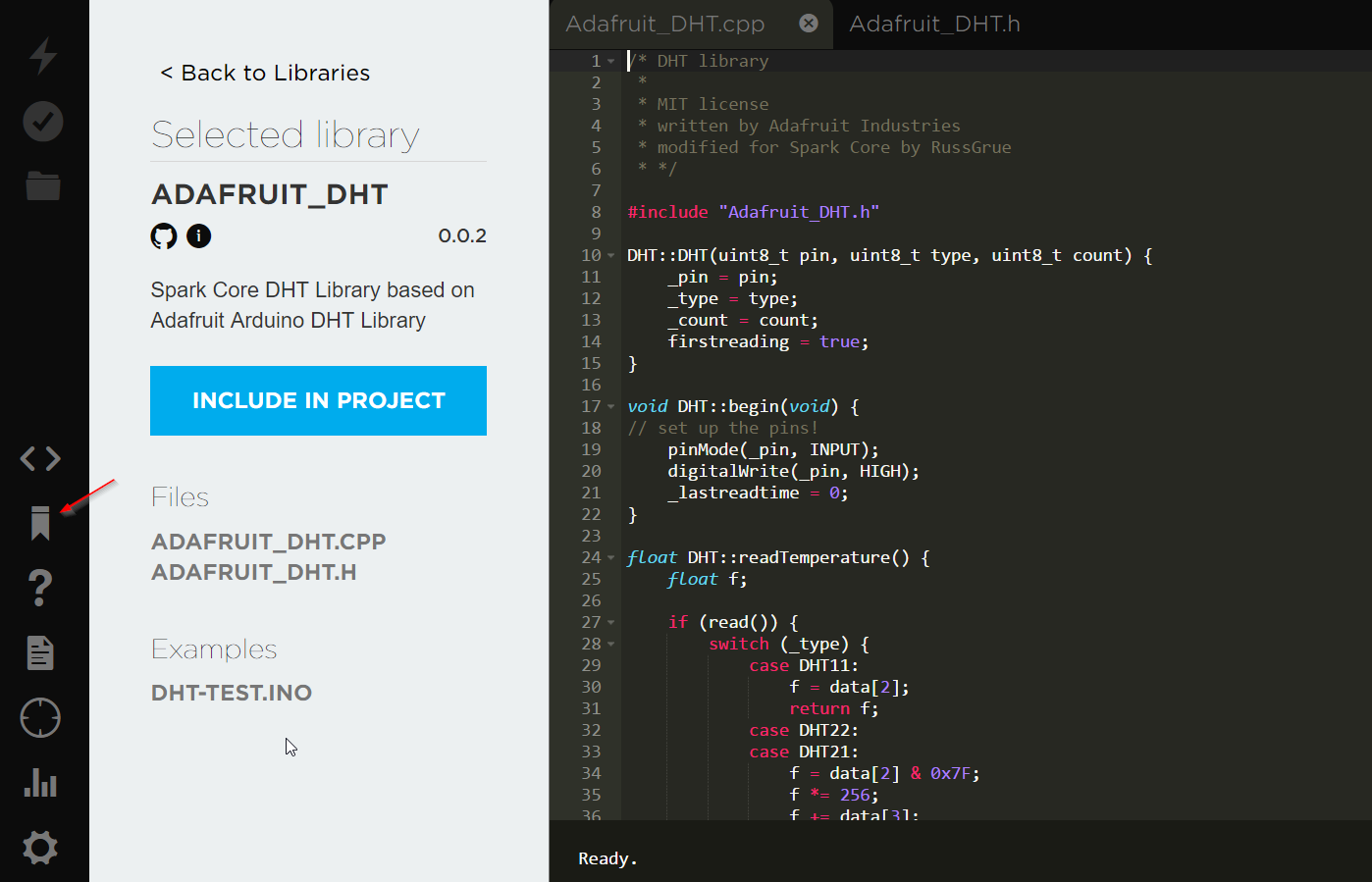
This sketch actually uses the Adafruit library and can be easily added from the Build Console. First create a new app and give it a name. Next, click the library icon, search for DHT and then select ADAFRUIT_DHT to end up in the screen below. Click Include in Project to include the library. When you are back in your app, copy and paste the code from above.
A few remarks about the code:
the #include was automatically added by the IDE when you added the Adafruit_DHT library
DHTPIN 1 means we connected the yellow data wire to pin D1; remember that the sensor sends a series of HIGH or LOW pulses to the pin
DHTTYPE DHT22 means we use the DHT22 sensor; the AM2302 I use is just the wired version of that sensor and has the same internals
I use getTempCelcius() but the library has functions for Fahrenheit as well
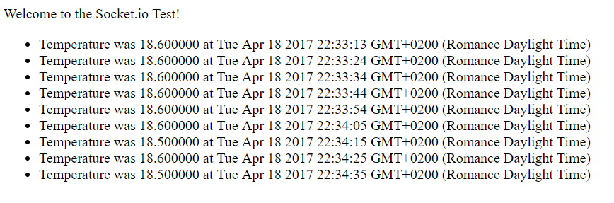
I also publish the temperature as a temperature event. If you still have the application of Chapter 1 running, you will get actual measurements in the socket.io client web page: